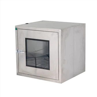
Hepa Air Cleaner Central Air Conditioning VRV
VRV is a variable refrigerant flow system. Since the Hepa Air Cleaner Central Air Conditioning VRV only delivers refrigerant to the extensions in each room, there is no need to design an independent air duct (the fresh air system arranges an additional air duct), which makes the equipment small and quiet. The system structure is similar to a split air conditioning unit, with one outdoor unit corresponding to a group of indoor units (generally up to 16 units). The control technology adopts variable frequency control to control the speed of the scroll compressor in the outdoor unit according to the number of indoor units turned on, and control the refrigerant flow.
Compared with the full air system, the full water system, and the air-water system, the VRV air conditioning system can better meet the personalized use requirements of users, the equipment occupies a relatively small building space, and is more energy-efficient.
Concepts and differences of VRV, VAV, VWV, and KRV
KRV: fresh air ventilator, full heat exchanger.
VAV: variable air volume air conditioning system, the terminal.
VWV: variable water volume (chilled water) air conditioning system.
MRV: fully variable multi-connected central air conditioning, which is also a variable refrigerant flow system in practice.
----------------------------VRV term explanation----------------------------
The VRV system is a variable refrigerant flow multi-connection system, that is, an air conditioning system that controls the refrigerant flow rate and achieves cooling or heating through direct evaporation or direct condensation of the refrigerant.
VAV term explanation
VAV variable air volume air conditioning system, like the fixed air volume air conditioning system, is also a kind of air conditioning method of the full air system. It controls and adjusts the temperature of a certain air-conditioned area by changing the air supply volume instead of the air supply temperature, so as to adapt to the change of the load of the air-conditioned area.
Its working principle is that when the load of the air-conditioned area changes, the system terminal device automatically adjusts the air supply volume sent to the room to ensure that the indoor temperature remains within the design range, so that the air supply volume of the air handling unit decreases at low load, and the air supply fan speed of the air handling unit also decreases accordingly, achieving the purpose of energy saving. The variable air volume system usually consists of air handling equipment, supply (return) air system, terminal device (variable air volume box), air supply port and automatic control instrument.
Generally, the VAV system should be used in the following systems: 1) In the same air conditioning system, the cold and hot, load differences and changes of each air-conditioned area are large, the low-load operation time is long, and the temperature of each air-conditioned area needs to be controlled separately. 2) The inner area of the building needs to supply cold air all year round.
----------------------------VWV terminology explanation----------------------------
VWV air conditioning variable water volume system, design Compared with the variable air volume system (VAV), VWV and VAV have many similar or even identical features. In specific engineering practice, even the "same" control strategy can be adopted.
For example: the variable frequency constant static pressure control of the VWV system and the variable frequency constant static pressure control of the VAV system are the same; and if the automatic control system can easily "capture" the opening of the water valve of the VWV system (just add a valve position sensor), then the variable static pressure control of the VWV system can also be realized. If the automatic control system can timely "measure" the flow of each end of the VWV system, then we can also realize the total water volume control of the VWV system.

----------------------------KRV Glossary----------------------------
KRV fresh air ventilator - total heat exchanger. The core component of the total heat fresh air ventilator is the total heat exchanger. The dirty air discharged from the room and the fresh air sent in from the outside exchange temperature through the heat transfer plate and humidity through the micropores on the plate, thereby achieving the effect of ventilation and maintaining stable indoor temperature and humidity. This is the total heat exchange process.
When the total heat exchanger is running in the summer cooling period, the fresh air obtains coldness from the exhaust air, which reduces the temperature, and is dried by the exhaust air, which reduces the humidity of the fresh air; when running in winter, the fresh air obtains heat from the exhaust air, which increases the temperature, and is humidified by the exhaust air. The fresh air ventilator is a kind of air ventilator that filters, purifies, and heat-exchanges the fresh air outdoors into the room, while filtering and purifying the polluted harmful gases in the room.
----------------------------Central air conditioning project installation----------------------------
1. On-site material stacking
Material stacking should be neat and orderly, and both ends must be sealed to ensure cleanliness. Copper pipes should be placed on a ventilated and dry shelf 300mm above the ground.
2. Outdoor unit installation
①. Selection of outdoor unit installation location
The air conditioner outdoor unit must be more than one meter away from the wall to ensure heat dissipation and sufficient maintenance space.
②. Foundation production
The foundation must be made in accordance with the installation dimensions of the equipment and have sufficient bearing capacity. The foundation must be level.
③. Outdoor unit in place
When hanging the outdoor unit, keep the machine level, and the contact part between the fuselage and the hanging rope should be padded to avoid wear or scratching the machine. The outdoor unit is padded with shock-absorbing pads at the installation holes and stress points in contact with the foundation, and fixed with nuts.
3. Indoor unit installation
①. Production and selection of hanging code
Determine the length of the hanging rod according to the indoor unit hoisting height and floor height and then cut the material.
②Indoor unit installation
a. Use an infrared locator to determine the installation position of the indoor unit boom, mark it, and drill a hole with an electric drill.
b. The indoor unit hoisting position should ensure that the air conditioning condensate can be discharged, the air duct is easy to install and the air supply is smooth.
c. A full threaded boom must be used, and the indoor unit must be fixed with double nuts to ensure that the machine is hung firmly.
d. After the indoor unit is hung, it must be adjusted horizontally.
e. When installing the throttling component, it must be installed vertically and horizontally. It is prohibited to tilt or invert it, and pay attention to the connection direction when connecting.
f. The indoor unit is wrapped with a dust cover to prevent a large amount of dust from entering the machine and affecting the machine's operation.
g. Ensure that there is enough installation and maintenance space around the indoor unit, and reasonably organize the return air flow.
----------------------------Refrigerant pipe construction----------------------------
①. Bracket installation
The distance between brackets should not be too large, and the installed brackets must be arranged neatly.
②. Refrigerant piping installation
a. Cut the copper pipe of the corresponding length with a cutter.
b. Clean the burrs at the port and the copper pipe chips in the pipe.
③. Refrigerant pipe protection
a. If the piping cannot be connected to the outdoor unit in time, it must be sealed to prevent dust, moisture, etc. from invading.
b. When the piping passes through the wall, a sleeve must be added for timely sealing protection.
④. Branch pipe installation
a. Branch pipes cannot be replaced by tees and can only be installed horizontally or vertically.
b. The horizontal straight pipe section between the copper pipe bend and the adjacent branch pipe is ≥1M.
c. The horizontal straight pipe section distance between the two adjacent branch pipes is 1M.
d. The horizontal straight pipe section distance between the branch pipe and the indoor unit is ≥0.5M.
⑤. Expansion pipe connection
The copper pipe diameter refrigerant pipe connection must be expanded, and the bell mouth expansion method is prohibited.
⑥. Expand the bell mouth
a. Use a bell expander to expand the bell mouth. The pipe mouth should be flat and free of burrs, and the bell mouth should be free of deformation and cracks.
b. Nut connection must be operated with two adjustable wrenches.
⑦. Nitrogen filling welding of refrigerant pipe
a. To ensure construction safety, the nitrogen bottle needs to be connected to a pressure reducing valve, and the nitrogen pressure is controlled at 0.2-0.3KGF/CM² during welding.
b. Determine the nitrogen path, insert the nitrogen pipe into the inlet of the refrigerant pipe to be welded and seal it, open the nitrogen bottle valve, adjust the nitrogen gas flow through the pressure reducing valve, and finally weld it.
⑧. Refrigerant pipe air tightness test
Connect the gas-liquid pipes together, lead out a pipe pressure gauge, and seal this interface. R22 uses 28KG/CM nitrogen to maintain pressure (R410A system uses 40KGF/CM²). Pay attention to the pressure correction before and after the pressure test. There will be a pressure change of +0.1KGF/CM² for every +1°. The temperature during the pressure test and the confirmed temperature must be recorded.
⑨. Blowing of refrigerant pipe
In principle, blow from top to bottom or horizontally, with a blowing pressure of 5KG/CM², to ensure that there are no impurities in the system.

----------------------------Use the following method to blow----------------------------
a. Hold a suitable plugging material against the main pipe opening on the air side of the indoor unit;
b. Use nitrogen to gradually pressurize the pipe. When the pressure increase cannot be resisted, suddenly release the pipe opening;
c. Repeat steps a and b for repeated blowing.
⑩. Refrigerant pipe insulation
a. Use a paper cutter to cut the insulation material larger than the gap. The end face of the insulation pipe needs to be coated with glue.
b. Pull the two ports apart, embed the insulation material, and glue the interface.
Keywords: Hepa Air Cleaner Central Air Conditioning VRV | industrial hepa filter system | small room hepa air purifier | filtrete hepa filter | h14 hepa filter air purifier | best air dust purifier